Solar drying
The demonstration plant includes a solar dryer with a treatment capacity of 275 kg/h of sludge from a Wastewater Treatment Plant (WWTP), with a moisture content at the inlet of approximately 80 %, getting values around 20% of moisture content at the outlet of the dryer. CIEMAT is in charge of its design, construction and operation. The solar dryer is based on the drying of sewage sludge inside a greenhouse using solar radiation and other indirect sources of low temperature heat, such as hot water and hot air. Thus, a flow of hot water from the electricity production prototype will be used for heating the dryer floor, through a radiant floor and for producing hot air in fan coils inside the solar dryer. The system is specially designed for the automatic drying of a wide variety of different biomass and waste materials. The innovation of this dryer lies in the integration of the different heat supply systems with a design that allows a stable continuous output in terms of humidity and maximization of the contribution of solar and waste energy which contributes to significant savings.
The dried sewage sludge will be stored in a hopper up to its utilization in the gasification plant, in the next step.
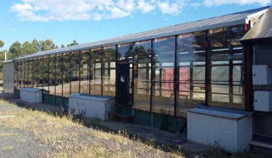
Solar drying pilot plant used within DRY4GAS project:
The hybrid solar drying pilot plant (CIEMAT patent No. ES 2379932) is based on the heating of biomass inside a greenhouse using solar radiation and other indirect sources of low temperature heat, such as hot water from boilers, engine cooling systems or heat exchangers from combustion or gasification equipment. The system is specially designed for the automatic drying of a wide variety of different biomass and waste materials. The innovation of this dryer lies in the integration of the different heat supply systems with a design that allows a stable continuous output in terms of humidity and maximization of the contribution of solar and waste energy which contributes to significant savings.
The size of the drying tunnel is 3.7 x 19 m and it has different elements to move the sludge and to transfer the heat to the mass to be dryed. The capacity varies between 20 and 60 kg / h of evaporated water, which is a function of factors such as product characteristics and weather conditions.
The Figure shows a schematic representation of the dryer with its different elements whose operation is described below:
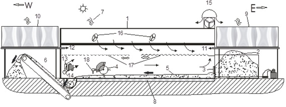
The sludge is fed to the greenhouse (1) from the east side through a silo (2) equipped with an underfeeding screw system (5). Once the biomass is inside the greenhouse, a tumbler (4) dumps and drags the material forming a uniform layer of adjustable height on the floor. The tumbler (4) is provided with a device (18) for measuring the biomass moisture content in different locations along the drying tunnel. The dried biomass is constantly collected at the West side by a chain conveyor, which dumps it in a covered shed (6). The greenhouse (1) is equipped with a floor heating system (8) fed with hot water. The air required for driving out the moisture (7) is taken from outside with inlet points (14) located in the West side. The air flows from West to East, i.e. in the opposite direction of the sludge flow. This air flow is caught by a fan extractor (15) located on the upper part of the greenhouse. In addition, fans (16) have been set up inside the greenhouse to prevent the accumulation of hot air in the upper part thereof.
With this technology, significant savings of conventional energy in drying can be achieved, estimated at a minimum of 15%, working continously and steadily during the year, or even greater, if working only during sunny hours. Investment and maintenance costs are low and the risk of fire is minimal, due to low working temperatures.
Gasification
The demonstration plant includes a gasifier to treat 67 kg/h of sludge from a Wastewater Treatment Plant (WWTP). CIEMAT is in charge of its design, construction and operation. The gasification reactor uses a bubbling fluidised bed technology. Gasification is carried out using air as gasifying agent. It operates at atmospheric pressure and autothermally, without the need for external heat input. The generated gas contains CO, H2, CH4 and other hydrocarbons that contribute to the calorific value of the gas. This gas is used in the energy recovery system of the demonstration plant.
The gasifier assembly has a series of equipment necessary to make possible the transformation of WWTP sludge from solar drying into gasification gas to be used in the energy recovery system. WWTP sludge is fed continuously to the reactor by means of a set of hoppers and endless screws. The gasification process used air from a blower. The fluid bed material can be dosed by an endless screw. In the gasification reactor, the WWTP sludge is converted into gasification gas and ashes. The major part of the ash are removed from the bottom of the reactor using a refrigerated endless screw. Gasification gas leaves the reactor at the top and passes through a cyclone system where the fly ashes are collected. The gas, free of particles, is directed towards the energy recovery system. In addition, the installation has a torch to burn the gas as safety system.
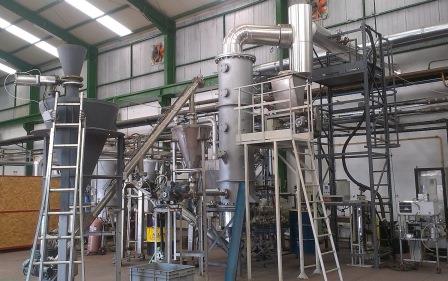
Biomass gasification pilot plant used within DRY4GAS project:
Bubbling fluidized bed gasification plant with a thermal capacity of 150 kWth. The gasifier, of 300 mm inner diameter, is pre-heated with a propane burner at the startup of the plant, but afterwards the process is autothermal, without any external heat source. A fan introduces air uniformly through the distribution plate, but other gasifying agents, such as water steam or oxygen, are possible.
The feeding system is airtight and consists of two hoppers and two screw conveyors. Moreover an additional hopper is connected to the gasifier for introducing the bed inert material continuously during the process, if needed.
The ashes removal from the bed is carried out by a refrigerated screw conveyor continuously, if necessary.
At the outlet of the gasifier, the gasification gas enters a cyclone, which remove the coarse particles. The gas without particles flows through a pipe with two sample points. Finally, the gas generated in the process is burnt in a torch.
A centralized control system allows the online measurement and saving of all operating parameters, such as temperatures, pressures and flow of biomass, air and gas. An online measurement of O2, CO, H2, CO2, CH4 and SH2, among other gaseous components, is carried out in the exhaust gases. The tar sampling in the gas is performed based on the technical specification CEN/TS 15439 and the concentrations of each component are determined in the laboratory.
Gasification gas combustion
The energy recovery assembly to be designed and manufactured by AITESA consists basically of a syngas combustion chamber and a gas-superheated water heat exchanger. As auxiliary components, it includes an exhaust gas recirculation system to the chamber and at the entrance of the exchanger, gas ducts between the chamber and the exchanger and between the exchanger and the chimney, as well as this latter equipment.
Combustion chamber:
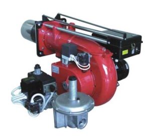
The combustion chamber is intended to generate a flow of hot combustion gases out of the syngas generated in the gasifier of the pilot plant. The chamber will have a gas recirculation system to regulate the gas outlet temperature without acting on the excess combustion air. The combustion chamber will be laid horizontally, with 1 propane burner of 103 kW. The chamber will be internally coated with a refractory for gas temperature of 1000 ºC and has a support bench in structural profiles.
Heat exchanger:
The heat exchanger will be of the gas economizer type, with vertical gas flow downwards the casing and the oil passing through horizontal tubes without fins, with flow direction upwards, in countercurrent with the gases. Before entering the exchanger, the combustion gases from the combustion chamber at 900 °C will be mixed with a flow of recirculated gases, in order to lower the inlet temperature to the exchanger to 600 °C. The heat exchanger shall be provided with a cleaning system using rotatory blowers of compressed air.
Electricity production
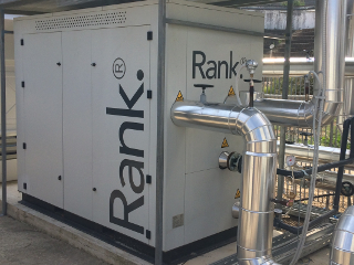
Rank® equipment allows the production of electrical energy and useful heat using a low-temperature heat source, through the use of a turbine on an organic Rankine cycle (ORC), with the associated economic and environmental benefits. Among the main applications of the Rank® ORC machines, we highlight the waste heat recovery and the utilization of renewable heat sources, with a special interest in cogeneration and trigeneration systems.
The Rankine Cycle is a thermodynamic cycle that converts thermal heat into mechanical work (that is converted into electricity), using water as working fluid. ORC or Organic Rankine Cycle technology uses an organic working fluid instead of water, in order to profit low-temperature heat sources. Rank® ORC machines use non-toxic and non-flammable working fluids, with low values of global warming potential (GWP) and zero ozone depletion potential (ODP). Rank® ORC products use high quality components and present high efficiency even at partial loads, increasing power produced and operational hours. Rank® equipment has plug-and-play connections for easy installation and user-friendly interface for easy operating and remote connection, with a control system that ensure maximized efficiency.
